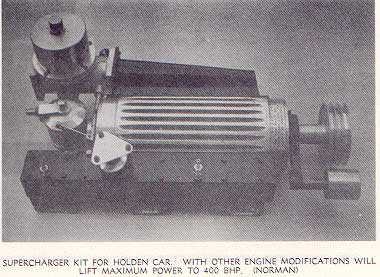
Supercharge!
0 to100 m.p.h. in 14 seconds in a HR Holden
by Eldred Norman

Chapter 10 - Fitting A Supercharger
At first glance some cars seem quite impossible to supercharge simply for space reasons. If you are the owner of one of those seemingly hopeless cases you can take comfort from the fact that I have never yet found a car in which it actually WAS impossible. Probably one of the most difficult is the very popular 'East-West' Morris series. One glance under the bonnet of one of these and most people would say that you would be lucky to get a packet of cigarettes in there without at least putting a 'power bulge' in the bonnet, and yet I have fitted a supercharger six inches in diameter and fifteen inches long and mounted it on a box section manifold with stub pipes straight into the inlet and driven by a single 'A' section belt, and with no structural alterations whatsoever.
The most satisfactory method of mounting is on a box manifold as near as possible, and feeding by short stub pipes direct into the ports. Generally speaking the further away the s/c is mounted from the inlet valves, the more the top end performance will suffer, although torque in the middle range will hardly be affected at all no matter how you mount the unit.
In the past one of the main difficulties in supercharging has been the lack of room provided by the manufacturer for a drive belt or belt. Fortunately this situation is changing. Many manufacturers now allow room for a drive to an air-conditioner compressor, and some even go so far as to provide an unused V on the crankshaft pulley for this purpose. The chapter on 'drives' will give you an indication of what you will need in this respect. In any case your first move must be to fit a suitable drive pulley to the crankshaft. This must be in addition to the normal generator, water pump setup. You cannot make one belt do the lot. Apart from the fact that arcs of contact become impossibly small if the belt is used to drive everything, you will find that the belt itself has already all it can do. Remember the fan and generator can require up to 4 b.h.p. on the average family car. The s/c must have its own belt.
Now quite possibly the fan will get partially in the way of the extra belt. This means that it must be moved towards the radiator to give belt clearance behind it. Probably this will bring it too close to the radiator for safety. Now either you move the radiator forward, (there is usually some latitude in this respect, and even a quarter of an inch can be useful), or you reduce the pitch on the fan blades. Where twin belt drives are involved you will almost certainly have to do both.
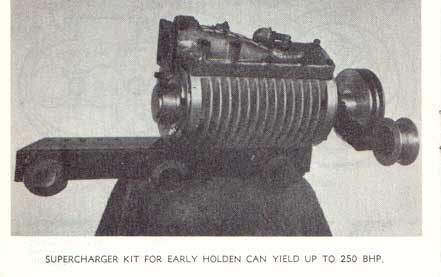
As I said before the supercharger should be mounted on a box manifold near the ports. Now to take the case of the H series Holdens. If the supercharger is mounted outside, as opposed to on top of, the box manifold, the drive belt from the crankshaft to the s/c pulley will be found to impinge against the boss of the water-pump pulley. However, this can be over come by fitting a tensioner to the back of the belt close to the water-pump. This serves a dual purpose in that it enables the belt to be tightened and it gives it clearance on the pump at the same time. To avoid the evils of ''back tensioning' the belt, I have tried making a special water-pump pulley and passing the s/c belts over the water pump pulley so that the s/c drive also drives the fan. The generator I drove with a separate short belt directly from its original crankshaft pulley. In this case the tensioner has to be put either inside or outside the load side of the drive belts, that is between the crankshaft pulley and the s/c. Unfortunately this triangulation of pulleys when using only a twin belt drive cannot transmit the necessary power with the H series, which of course require a fairly large s/c. This same drive can be used with complete satisfaction on the smaller early model Holden. In this case however the s/c needs to be mounted on top of the box manifold. The higher bonnet line of the early models permits this.
Belt tensioners are best made in the form something like a car connecting rod. The 'big end' is clamped around the bearing boss at the shaft end of the s/c. This permits the tensioner arm to swing in a complete circle around the shaft, and permits tensioning in any position. The tensioner pulley itself is mounted on a ballrace and shaft which is in turn 'fixed' in some way in the piston pin end of the rod.
The pressure manifold itself is best made out of box tubing. Three by two by ten gauge is the size I most commonly use. This has sufficient capacity to act as a small reservoir or plenum chamber which permits the accumulation of the charge against the pulsations caused by the individual cylinders breathing. This manifold should be fitted with a relief valve of the largest practical dimensions, and positioned as near to the s/c outlet as possible.
All cars backfire at times. With the supercharged car and the pressurised manifold a backfire can do considerable damage to the supercharger if no relief valve is fitted.
It is not generally realised that even with a large relief valve the manifold pressure will momentarily rise to at least 100 p.s.i. due to the valve inertia factor, and even though the valve was set to 'blow off' at only 20 p.s.i. Of course this can cause a very sudden shock load to fall on the drive. With V belts this does not matter, they can slip. With chain or tooth belt drive it can bend a supercharger shaft or more likely in the case of the Gilmer type belt, strip the rubber teeth or break the belt. Some sort of friction drive can usefully be employed with these last two methods of driving.
When fabricating supercharger manifolds, both inlet and outlet, remember to make provision for accessories such as brake boosters, boost pressure gauges, water injection, pressurised fuel tank, etc. it is as well to provide two tappings on the inlet side and no less than four on the pressure side.
Good 'flow through' with the inlet manifold is of course vitally important as well as adequate carburation. In one instance I encounted, three Holden Stromberg carburetors had been mounted on a tee piece (it is very restrictive) to feed the supercharger. With this setup maximum boost was 5 p.s.i. A modification to this arrangement lifted boost pressure to 15 p.s.i without altering the supercharger drive rate at all. This resulted in an extra 100 b.h.p.
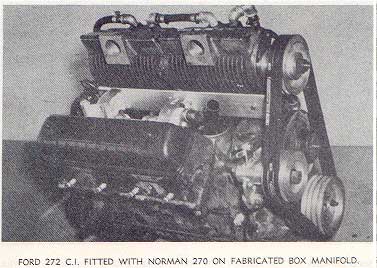
When it comes to supercharging a V8 they can be simple or difficult depending on the position of the distributor. With G.M. products the distributor is at the back of the engine which means that it usually possible to mount the s/c in a forward position and the drive itself is thus more or less unobstructed. This was also so of the early overhead Fords. Unfortunately, the present series are much more difficult because the distributor is 'right in the way'. There is quite a lot of work in fabricating a complete new manifold to sit between the two banks of cylinders. Water galleries have to be blanked off or by-passed. Probably the simplest way is to use the standard manifold and 'butcher it'.
It will be necessary to mill out a channel deep enough to expose all the port passages, and wide enough to take a prepared box on which the s/c can be mounted. The box of course will have to be brazed or welded into the old manifold. This should be done while the manifold is bolted into position on a block as it will most certainly try to warp during the welding process.
Now superchargers are mostly only provided with a series of tapped holes in the casing itself and a problem immediately arises. How to fix the s/c to the box since it is impossible to get inside the box to attach the s/c. In some cases, it is possible to run the bolts right through the box and then mount the whole as an assembly on the ports. If it is not possible a flange wide enough to permit bolt accessibility will have to be welded to the box manifold, and a matching flange will have to be bolted to the s/c itself. As an alternative to this the box manifold which is welded into the original manifold can be made very high and not very 'thick'. In this case the s/c can be bolted to the side of the box. The former method is to be preferred as it permits a more direct air/fuel path. However the latter method will permit the supercharger to be mounted in such a way that the unit and drive clear the front mounted distributor on the later model Fords.
Fortunately all V8's have ample room for the belt system when it comes to fan and radiator clearance.
With small cars and small superchargers, when the manifold to supercharger bolts would seemingly be inaccessible, the supercharger can be satisfactorily mounted if provided with a couple of locating dowels, and then clamped down to the manifold with an exhaust pipe style clamp bracket over the bearing boss at each end. To make absolutely sure that there are no leaks a gasket of one sixteenth Lurine should be used with this method of mounting.
Where the original manifolding has to be employed a great increase in top speed is not likely unless the car is fitted with an overdrive or else the gearing is raised to take advantage of the extra torque available. This is the case with the 6 cyl. Falcons in the Ford range. Unless the original manifold which is cast integral with the head, is entirely removed and new separate flanges welded to the ports, any supercharge with these models must pass through the original carburetor mounting flange ports. Maximum torque under these conditions may well be doubled but maximum b.h.p. is only likely to rise about 35 %.
With these models it is simplest to bolt a box to the existing carburetor mounting flange, and extending it forward about 12 ins. The box will have to be modified where it bolts onto the flange as the latter is tilted to keep the carby vertical on a sloping motor. The box of course must follow the slope of the motor so that the s/c when bolted to it follows the same belt alignment as the belt system on the engine. The drive for this will require a twin extension to the crankshaft pulley and a new double pulley to replace the one for the fan. The drive belts go around crankshaft, s/c and fan pulley, with a tensioner on the back side of the belt between the crankshaft and s/c pulley. The generator will be driven by a new shorter belt from the original crankshaft pulley to the generator without going round the fan pulley.
As I said at the beginning of this chapter ANY car can be supercharged. If yours seems difficult, just sit down and think. Once you have got it properly supercharged you'll realise that all other forms of 'hotting up' are only a shadow of the real thing
The End
Eldred Norman
Noosa heads, Qld
October, 1969
 |
|
|
This is a special Technical Info article, reprinted from the original (and rare!) book that was supplied with superchargers purchased from Eldred Norman, Aussie racing legend and manufacturer of Norman Superchargers.
Although not a common method of modifying an FE or FC, the theory and information about fuel induction, carburettion and so on is fascinating. Many thanks to Tony (IhadaV8) for obtaining the book and providing it to us. Tony in turn thanks Mike Norman, for supplying a copy of his father's book.
Important Note: This document is intended as a guide for those persons interested in repairing or modifying their vehicle. The FE-FC Holden Car Clubs of Australia take no responsibility and accept no liability for the information contained herein. You must ensure that all work carried out and/or modifications made to your vehicle are legal in your state, and we recommend you contact an engineer or your local Traffic Authority for further information.
If you have a technical question about repairs or maintenance on your FE or FC, please post a question on our Discussion Forum.
Home || NSW || Queensland || SA || Victoria || Sign the Book || Chat about FE/FCs || Nationals || Tech Data